Multi-stage analog signal processing circuit to distinguish bass, midrange, and treble frequencies from raw microphone input using op-amps, diodes, filters, and more.
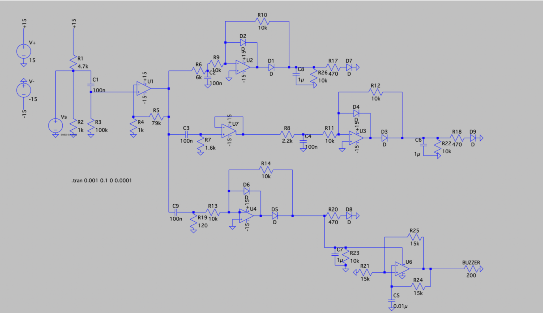
LTspice Full Circuit Diagram
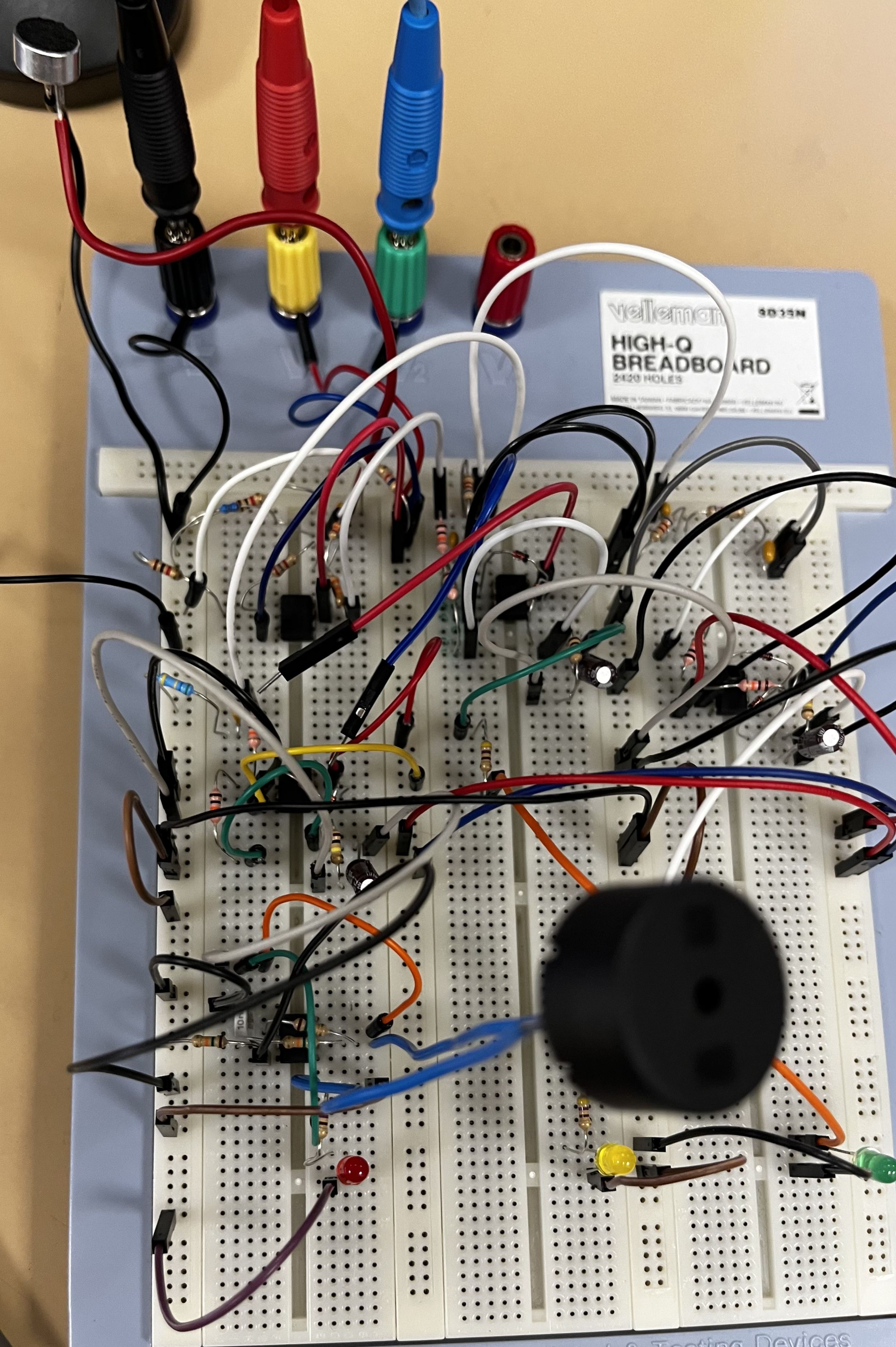
Physical Prototype
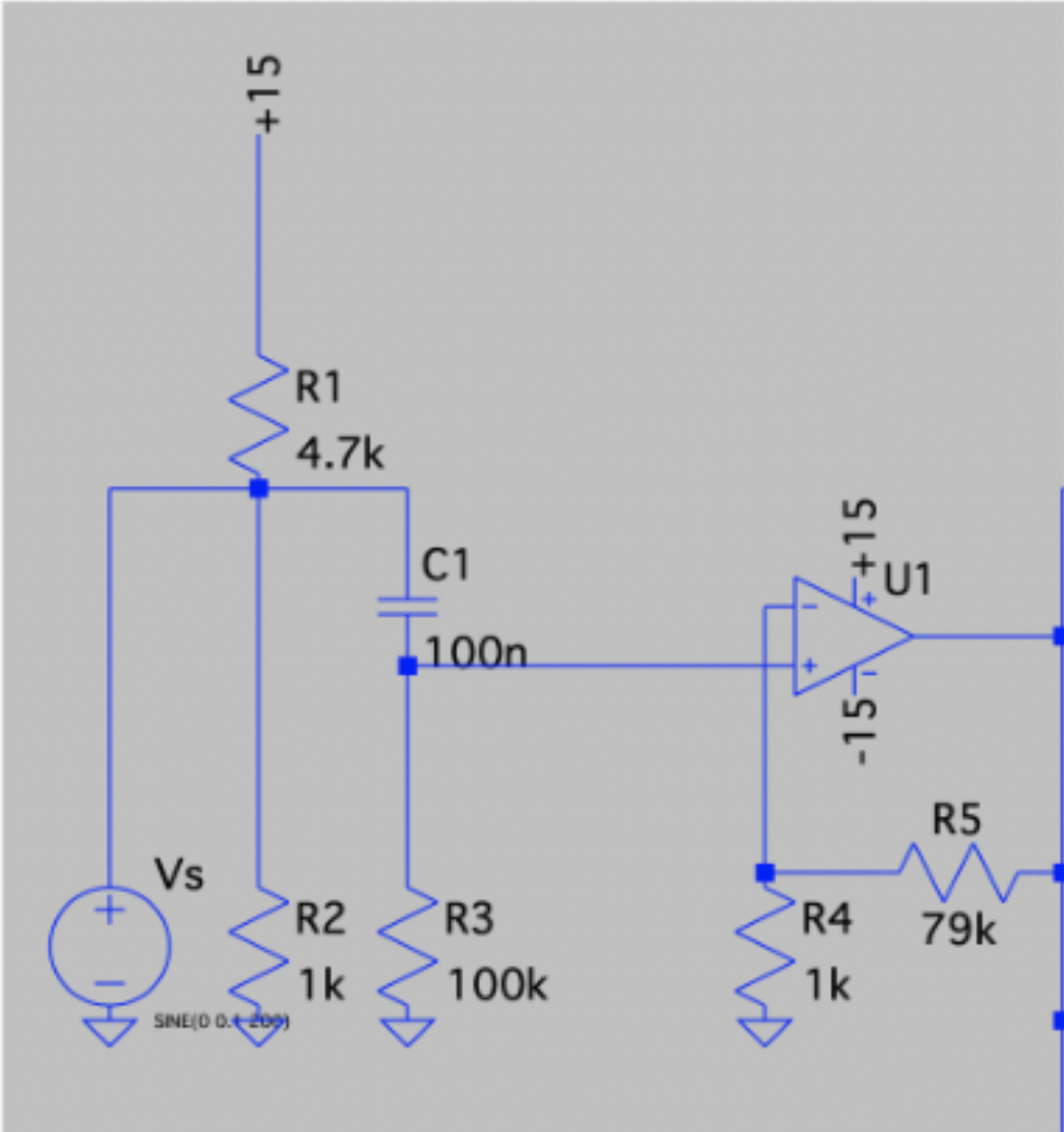
Microphone Input:
Takes in raw audio input, divides the voltage to establish a reference, and enters a high-pass filter to block DC offset. Amplifies the signal 80x from ~200 mV peak-to-peak to ~8 V using an LM741 Op-Amp.
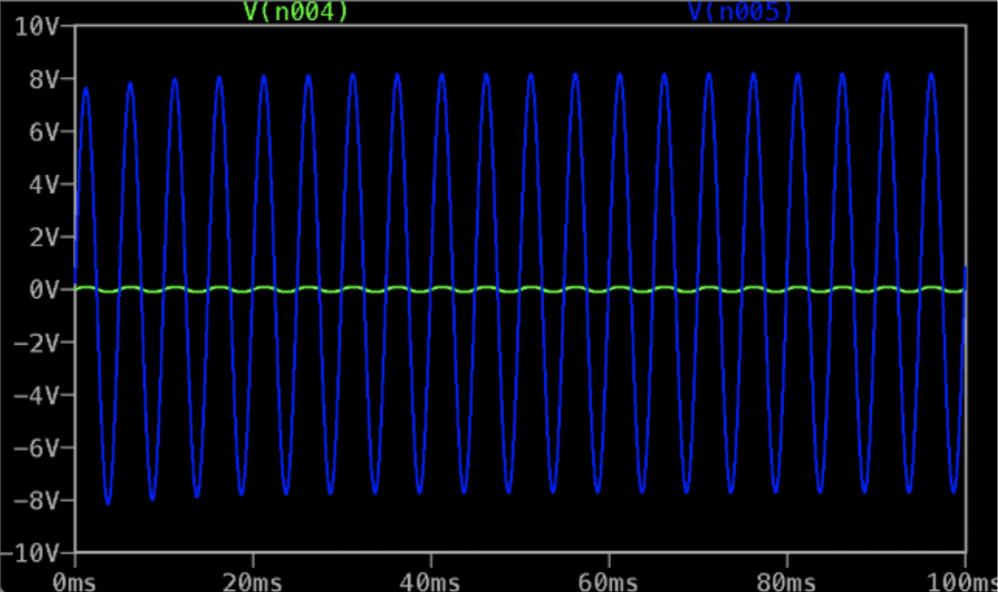
Vi vs. Vo — 80x Amplifier
Filters:
The resulting audio will pass through 3 filters: a high-pass filter for treble, a low-pass filter for bass, and a band-pass filter between those for the remaining middle frequencies.
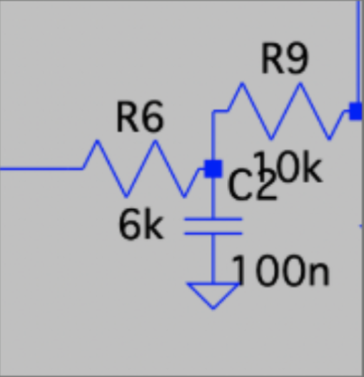
Low-Pass Filter: 265 Hz
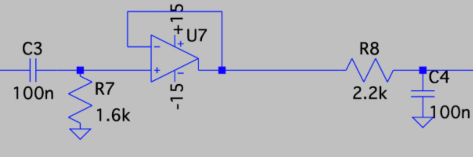
Band-Pass Filter: 750 Hz - 1 kHz
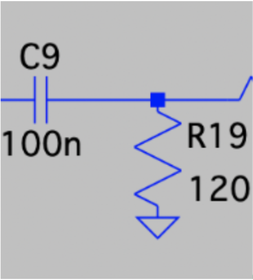
High-Pass Filter: 13 kHz
Experimentally, the filters had ranges of < 300 Hz, 400-2800 Hz, and > 3 kHz, respectively. The frequency graphs below show the three filter voltage outputs at a given input frequency and demonstrate that the filter with the appropriate range yields the strongest output signal.
Green - Low Pass, Blue - Band Pass, Red - High Pass
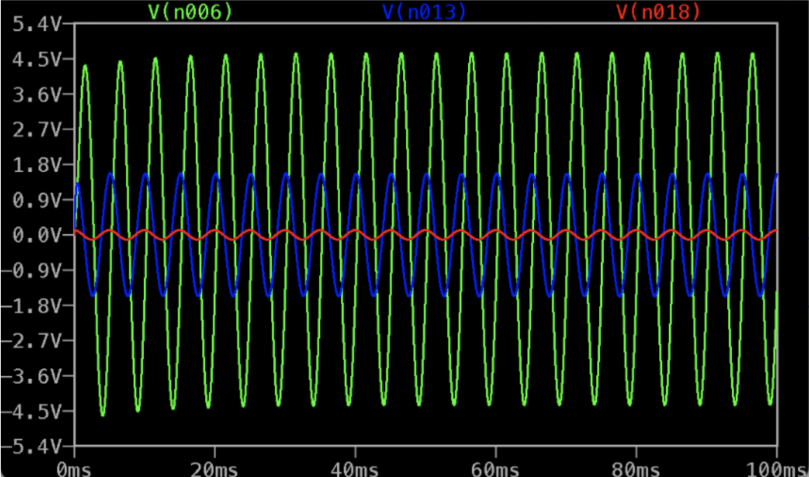
200 Hz Input
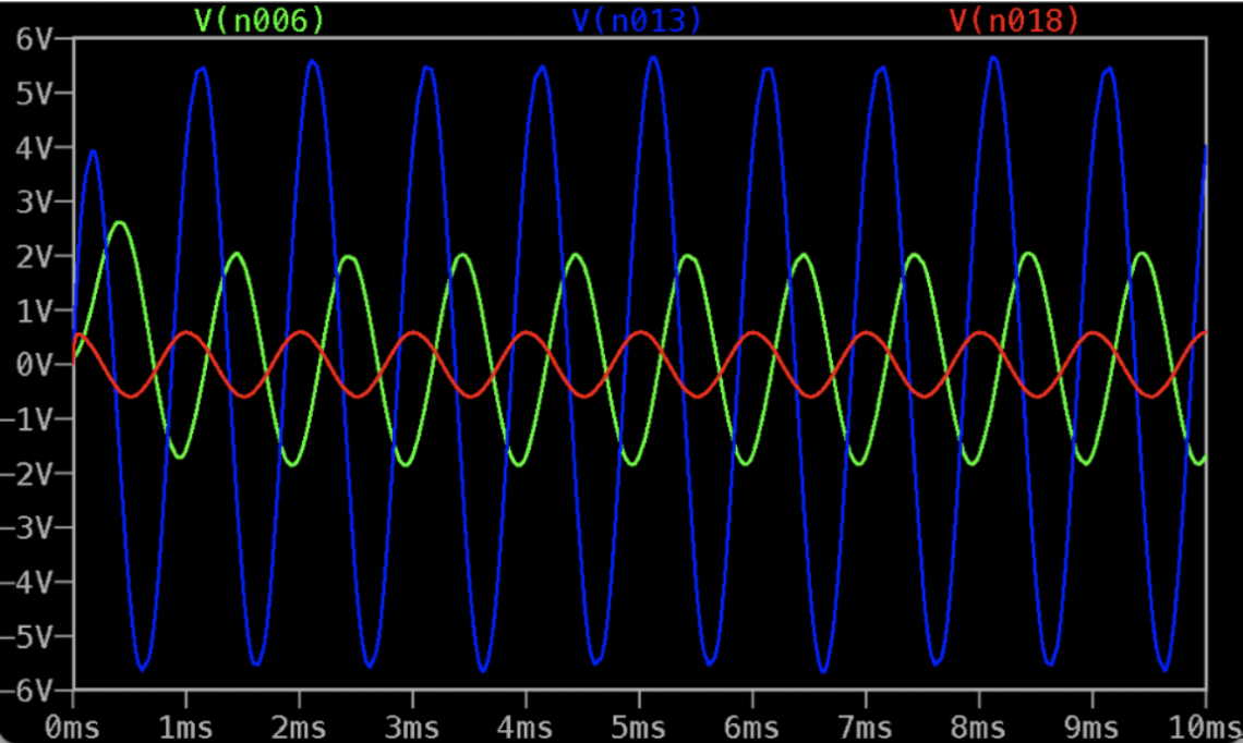
1 kHz Input
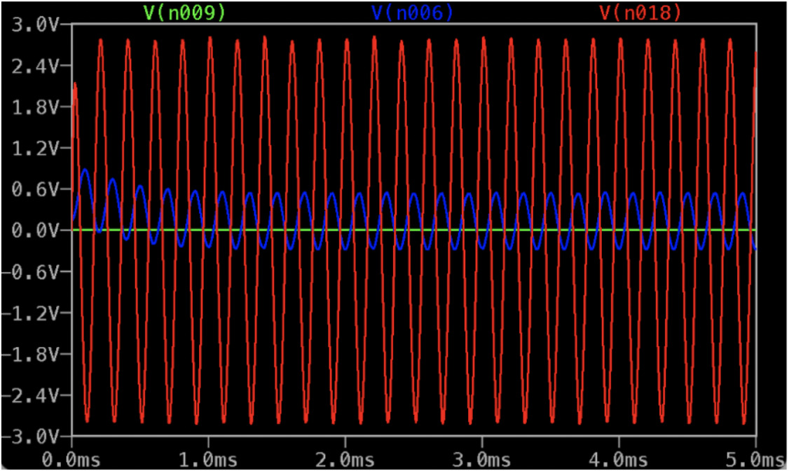
5 kHz Input
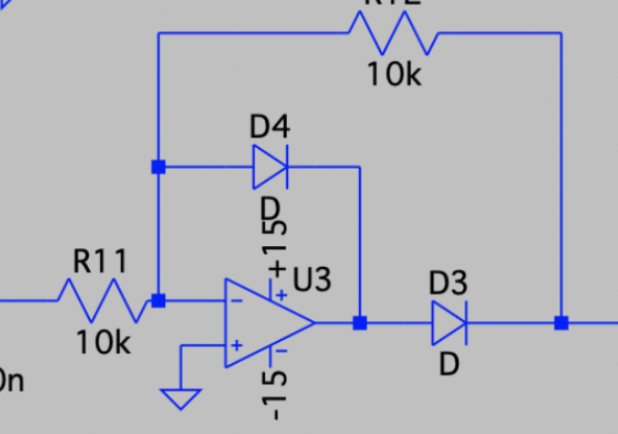
Rectifier Circuit
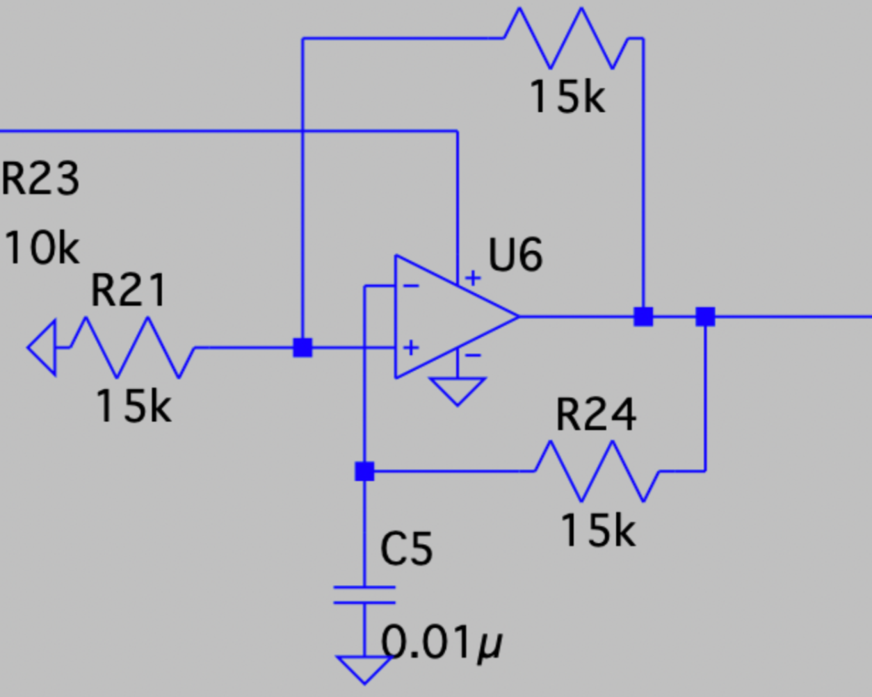
The signal goes through a half-wave precision rectifier in each branch, effectively removing the negative amplitude. One diode at the Op-Amp output only allows one polarity, and the other activates when the first turns off, preventing the Op-Amp from railing to 15 V.
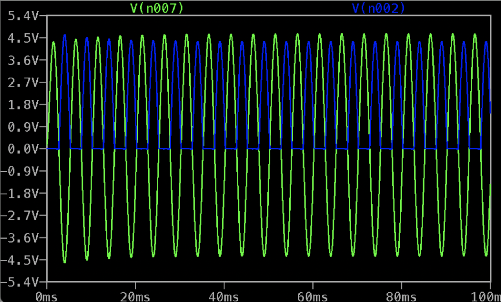
Rectifier Output Signal
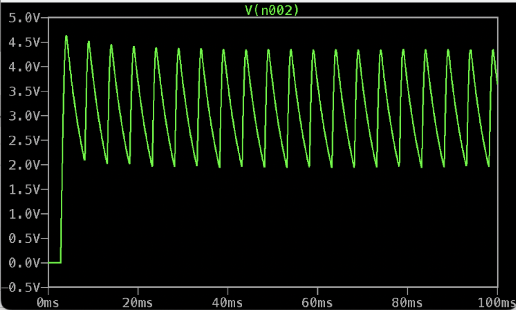
Peak Detector Output Signal
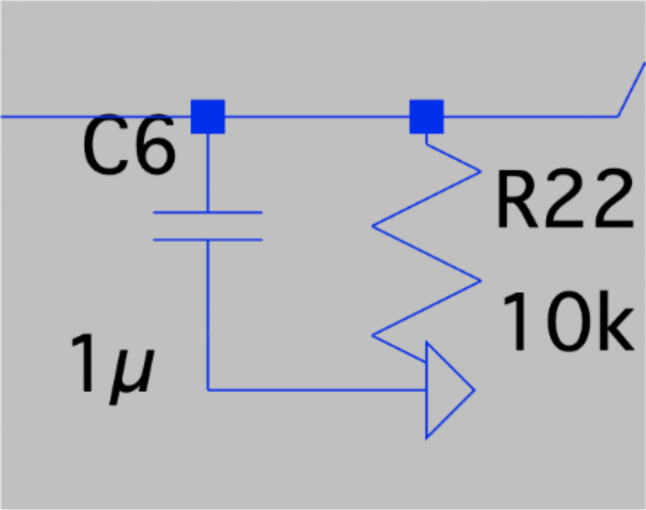
Peak Detector
The detector utilizes a capacitor of 1uF to charge to the peak voltage, which then slowly dissipates through the 10 kΩ resistor, smoothing the resulting signal.